

 Spanish
  French
  German
  Simplified Chinese
 Homing / Home Inputs
Homing the machine is one of the most important parts of a CNC. Without homing the machine no CNC machine can be used to its full potential and can result in the crashing of the machine as the controller does not know the position of the axis on power-up. This page shows how to set up homing on your machine.
For additional information on how to start the homing process please see: How to home your machine
PLEASE NOTE: The sensors shown in the video below show a separate 5-volt power supply. New version sensors such as the Masso Homing Sensor can run on a wide range of voltages and may be powered directly from the Masso power supply without the need for a separate power supply. Please consult the datasheet for your homing sensor to determine its required operating voltage.
Step 1: Mounting sensors
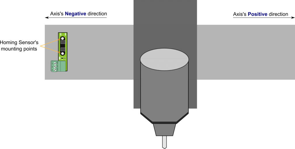
Mount homing sensors/switches on each axis of your machine as shown in the below image. It's preferred the sensors/switches are mounted on the 0.00 location of the axis but can be mounted at any location.
Step 2: Assign inputs
After wiring the sensor/switches the system must be configured for proper operation as described below:
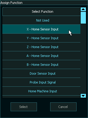
- Go to the F1-Setup screen.
- From the INPUTS list select any free input and assign them as X, Y, Z... Home sensor Input.
- You can also see the status of the sensors change from L to H when a signal is received on that input from homing sensor/switch.
INFORMATION: All input signals can be easily inverted by selecting the input in the INPUTS list and pressing the space-bar key on the keyboard to invert the input signal. These settings are automatically saved.
CAUTION: The homing inputs must show a LOW signal when the sensor/switch is not engaged or the homing will fail.
Step 3: Setting up the homing sequence
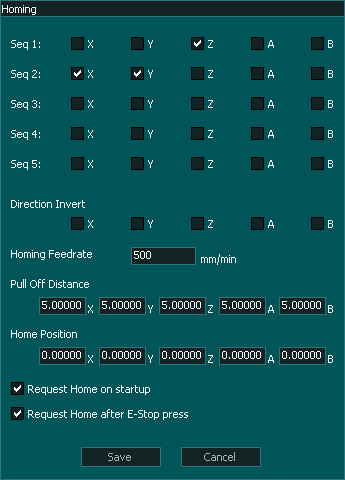
- Open the Homing window.
- Now in the homing sequence tick the appropriate boxes for the axis as you would like to home.
- In the below example we set the homing sequence for a milling machine/router. As you would first need to move the tool away from the job by moving the Z-axis up, set Seq 1 by only selecting the Z axis, this way MASSO only homes Z axis first.
- Next in Seq 2 select the X and Y-axis to start homing the X and Y axis together.
- When an axis is slaved it will appear grayed out in the homing screen.
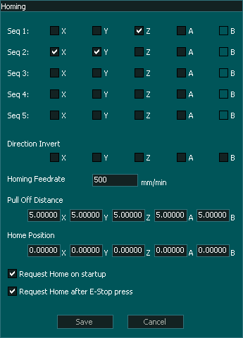
Step 4: Setting homing direction
During homing if any of the axis starts moving away from the homing sensor/switch, press ESCAPE or feed hold button to stop homing cycle and invert the direction in the homing setting as shown below.
In the Examples below the X-axis homing direction has been inverted.
- When inverting the homing direction of a slaved axis please make sure that both axis have the same setting for the axis that make up a slaved pair or they will travel in opposite directions.
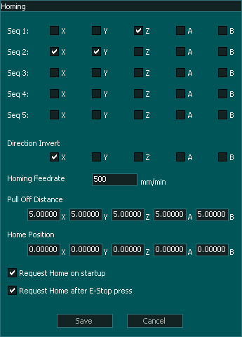
Step 5: Pull off Distance
Step 6: Specifying the homing location
As the homing sensors/switches can be mounted on either side of the axis, the position of the homing sensor/switch needs to be entered. If the sensor/switch is mounted on the 0.00 location as per the above example then enter Home Position as 0.00. If the sensor/switch is mounted on the other side, for example, the axis travel is 400mm and the sensor/switch is mounted at 400mm location then set Home Position as 400.0
INFORMATION: It's a good idea to set to enable "Request Home on startup" and "Request Home after E-Stop press" option in the "Homing settings" window. This will blink a homing request alarm on the screen to tell the user to home the machine before use and won't let the user run and gcode without homing the machine.
Wiring the Masso Homing sensor
Information on wiring the Masso Homing sensor
If you are using a third party homing sensor please see our Quick start guide on identifying and connecting.