Spanish
  French
  German
  Simplified Chinese
 EStop Wiring
WARNING: To avoid damage to equipment or hazard to personnel, the system installer should wire the E-Stop button so that pressing the E-Stop button disables all drives and actuators on the machine. The E-Stop relay output on the MASSO should be wired to disable the axis drives and the spindle drive circuits.
Simple one E-Stop button wiring
WARNING: It is critical that inductive loads such as Motor brakes and Relays are not connected directly to the E-Stop button circuit as doing so will cause damage to the E-Stop circuit. If you need to operate a brake or similar please connected it via the ES output using the MASSO Relay Module.
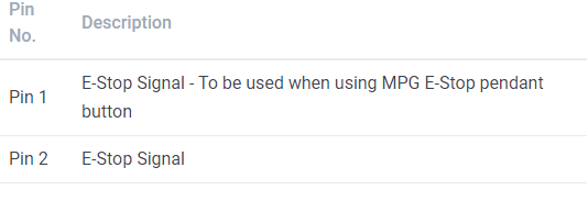
If using Touch Wiring module with external E-Stops at the Machine end only use Pin 2 on the E-Stop terminals
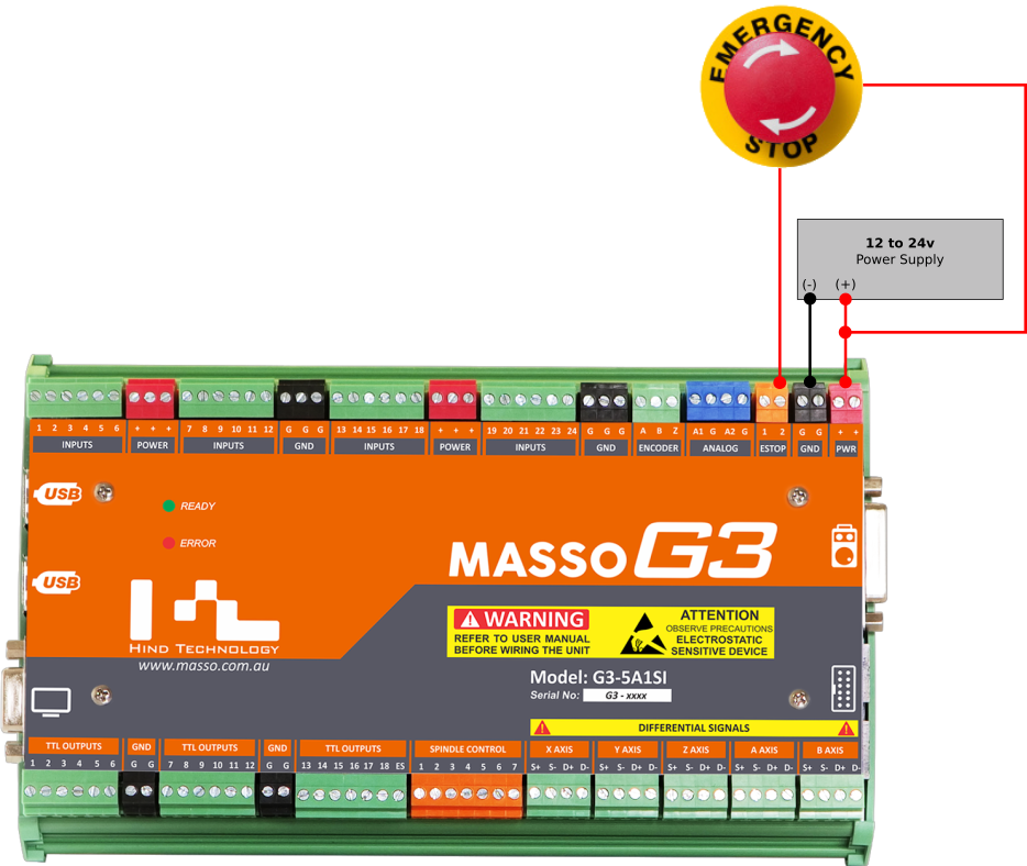
The below wiring example shows how to wire and use only one E-Stop button. The E-Stop button is wired to ESTOP terminal Pin 2.
In the below example E-Stop button on the MPG will not work. If using a Pendant please use one of the connection methods shown below.
Wiring only one E-Stop on MPG pendant
WARNING: It is critical that inductive loads such as Motor brakes and Relays are not connected directly to the E-Stop circuit as doing so will cause damage to the E-Stop circuit. If you need to operate a brake or similar please connected it via the ES output using the MASSO Relay Module.
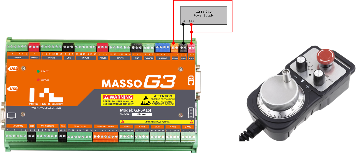
The below wiring example shows how to wire and use only the E-Stop button on the MPG pendant. Pin 1 on the ESTOP terminal is wired to positive of the power supply to get the MPG E-Stop button working.
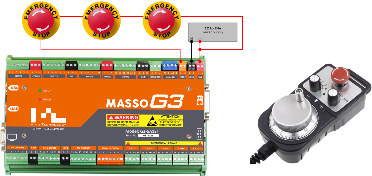
Wiring multiple E-Stop buttons and MPG pendant E-Stop button
The below wiring example shows how to wire and use multiple E-Stop buttons and MPG pendant E-Stop button. All E-Stop buttons are wired in series to Pin 1 on the ESTOP terminal through the positive of the power supply. When any of the three external E-Stop buttons or MPG pendant E-Stop button is presses, MASSO will display an E-Stop alarm on the screen and the "ES" (E-Stop output) singnal will go LOW.
Wiring E-Stop output signal to relay
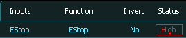
A special output signal "ES" (E-Stop output) is available on the outputs terminal. This output is internally hardwired to the E-Stop button signals and goes LOW when the E-Stop button is pressed.
- The output voltage of this output is 2.3 volts and drops to 0v when the Estop button is pressed. This means that the Estop relay is permanently on when the Estop is released and the relay turns off when the Estop is pressed. This provides fail safe operation.
- This output is used to control a relay and then the relay disables all drives and actuators on the machine. The user should not rely on the software to stop the axis, spindle or other actuators in case of an emergency and must disable all drives electrically.
- The normal state of the ES Relay is energized when the machine is not in an EStop condition.
- Multiple relays can be used if you need more than 1 set of relay contacts
- Up to 2 MASSO relay inputs can be connected to the ES output however if you require more than 2 relays connect them as shown below.
- You can connect multiple MASSO Relays together as shown. Use this method of wiring if you require 3 to 5 relay outputs. Relay 1 is connected to the ES output on MASSO and the Output of Relay 1 will operate all other relays.
- A single 3.3K 1/4 Watt resistor will work to operate 2 to 5 relays on the same MASSO Relay Module.
INFORMATION: MASSO Relay Module information is available here: MASSO Relay Module
Caution: The disable methods for the devices in the diagram below are for demonstration purposes only, to show various connection methods. Please consult your user manual for the correct method to disable and enable your device.
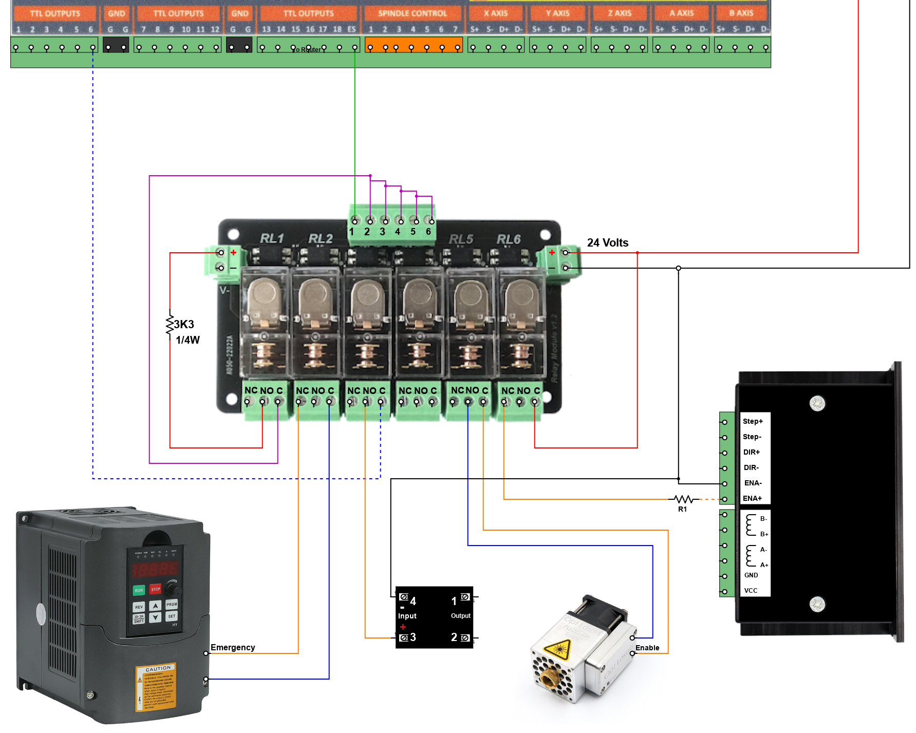
WARNING: If you are disconnecting mains power in an EStop situation it is highly recommended that you do not run the mains through the MASSO Relay. Use the relay to operate a separate relay located elsewhere in the control cabinet. This is so that you are not mixing Low voltage signal and Mains voltages on the same board as this can lead to accidents. It is best practice to keep your mains voltage circuits separate and physically protected against accidental contact by the user.
This video explains the EStop switch install process
Troubleshooting